Continued from Signals and Systems Unit Impulse and Unit Step Functions
Signals & System Continuous and Discrete Time Systems
System
A physical system explained in the most simplest way is interconnection of components, devices or subsystems.
In contexts ranging from signal processing and communications to electromechanical motors, automotive vehicles, and chemical-processing plants, a system can be viewed as a process in which input signals are transformed by the system or cause the system to respond in some way, resulting in other signals as outputs.
For example, a high fidelity system takes a recorded audio signal and generates a reproduction of that signal. If the hi-fi system has tone controls, we can change the tonal quality of the reproduced signal.
Continuous Time System
A continuous-time system is a system in which continuous-time input signals are applied and result in continuous-time output signals
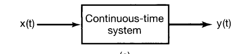
Discrete Time System
Similarly, a discrete-time system-that is, a system that transforms discrete-time inputs into discrete-time outputs.
Examples of Systems
Circuitry
Consider the RC circuit depicted If we regard as the input signal and as the output signal, then we can use simple circuit analysis to derive an equation describing the relationship between the input and output. Specifically, from Ohm’s law, the current through the resistor is proportional (with proportionality constant ) to the voltage drop across the resistor; i.e., Similarly, using the defining constitutive relation for a capacitor, we can relate i(t) to the rate of change with time of the voltage across the capacitor:
Bank
As a simple example of a discrete-time system, consider a simple model for the balance in a bank account from month to month. Specifically, let denote the balance at the end of the nth month, and suppose that evolves from month to month according to the equation.
where represents the net deposit (i.e., deposits minus withdrawals) during the nth month and the term models the fact that we accrue 1% interest each month
Big paragraph
-
Broad Applicability of Tools:
- Systems across various applications often share common characteristics.
- Effective tools for signal and system analysis are developed by identifying these common characteristics.
-
Characteristics of Useful Systems:
- Property and Structure: Systems should have exploitable properties and structures for gaining insights and developing analysis tools.
- Modeling Practical Systems: Many practical systems can be accurately modeled using the identified class of systems.
-
Focus on Linear Time-Invariant Systems:
- The book will focus on linear, time-invariant (LTI) systems due to their:
- Useful properties and structures.
- Broad applicability to practical systems.
- The book will focus on linear, time-invariant (LTI) systems due to their:
-
Modeling and Idealizations:
- Models represent idealizations of physical systems.
- Accuracy of Analysis: The quality of analysis depends on the accuracy of the model.
- Examples:
- Resistor: Linear model (Ohm’s Law) is idealized but accurate for many applications.
- Capacitor: Linear model (Capacitance) is an idealization, accurate within specified conditions.
- Friction: Linear retarding force as an approximation with a range of validity.
-
Importance of Model Validity:
- Range of Validity: Ensure that models and analyses remain within the conditions where assumptions are valid.
- Engineering Practice: Identifying and respecting the limitations of models is crucial for effective application and analysis.
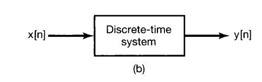
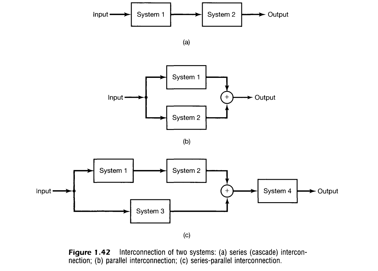
Interconnections of Systems
An important idea that we will use throughout this book is the concept of the interconnection of systems. Many real systems are built as interconnections of several subsystems. One example is an audio system, which involves the interconnection of a radio receiver, compact disc player, or tape deck with an amplifier and one or more speakers. Another is a digitally controlled aircraft, which is an interconnection of the aircraft, described by its equations of motion and the aerodynamic forces affecting it~ the sensors, which measure various aircraft variables such as accelerations, rotation rates, and heading~ a digital autopilot, which responds to the measured variables and to command inputs from the pilot (e.g., the desired course, altitude, and speed)~ and the aircraft’s actuators, which respond to inputs provided by the autopilot in order to use the aircraft control surfaces (rudder, tail, ailerons) to change the aerodynamic forces on the aircraft. By viewing such a system as an interconnection of its components, we can use our understanding of the component systems and of how they are interconnected in order to analyze the operation and behavior of the overall system. In addition, by describing a system in terms of an interconnection of simpler subsystems, we may in fact be able to define useful ways in which to synthesize complex systems out of simpler, basic building blocks.
Information
- date: 2024.08.20
- time: 05:01
- Continued to Signals & System Basic System Properties