Continued from lecture Computer Organization and Architecture Lecture 6
Architecture and Organization in the Context of Fetch and Decode Cycles
The fetch and decode cycles are an integral part of the architecture and organization of a computer system, directly tied to its control unit, memory hierarchy, and registers. Understanding how these components work together provides deeper insight into how instructions are processed at a hardware level.
Key Components in the System Architecture
- Program Counter (PC):
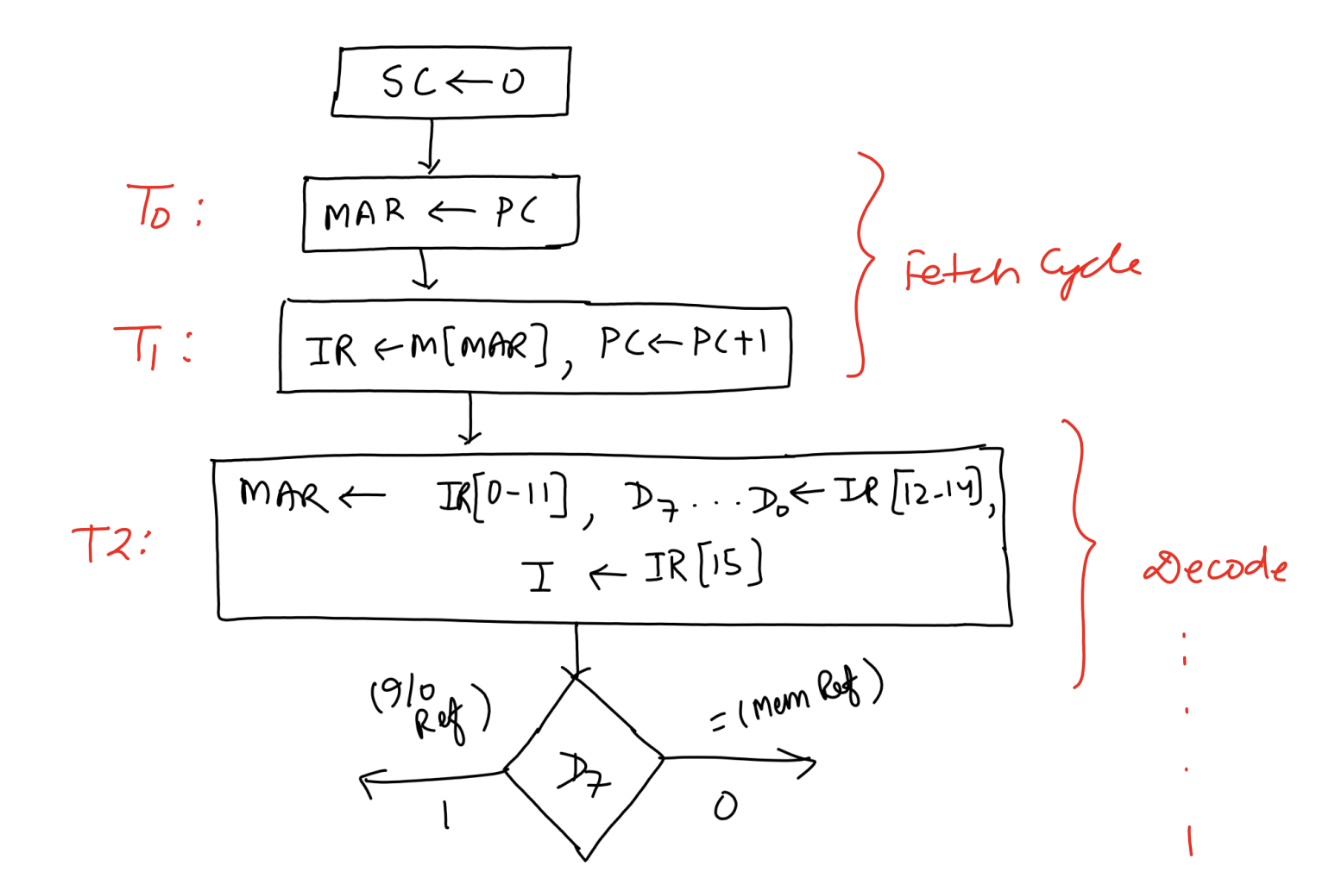
- The PC is a special-purpose register that holds the address of the next instruction to be fetched. It plays a crucial role in ensuring the sequential execution of instructions, except during branch or jump operations when it is explicitly updated.
- The PC interacts closely with the Memory Address Register (MAR) during the fetch cycle.
- Memory Address Register (MAR):
- The MAR acts as the bridge between the CPU and memory. It holds the address of the memory location that is currently being accessed.
- During the fetch cycle, the PC loads its value into the MAR, indicating where to fetch the instruction.
- Instruction Register (IR):
- The IR temporarily holds the fetched instruction before it is decoded. This ensures that the instruction is readily available to the control unit for decoding and further action.
- The IR splits the instruction into its functional components, such as the opcode and operand address.
- Control Unit (CU):
- The control unit orchestrates the fetch and decode cycles. It generates control signals to:
- Access the memory.
- Transfer data between registers.
- Decode the instruction for further action.
- The CU also interprets the addressing mode (direct or indirect) and determines the type of instruction (memory reference, I/O, etc.).
- The control unit orchestrates the fetch and decode cycles. It generates control signals to:
- Memory Hierarchy:
- The instruction fetch cycle relies on the memory subsystem, starting with the main memory (RAM) where instructions are stored.
- The efficiency of instruction fetches is often improved by using cache memory, which stores frequently accessed instructions and data to reduce latency.
- The organization of memory into smaller, faster levels (L1, L2, L3 cache) ensures quicker instruction retrieval for the CPU.
- Bus System:
- The address bus carries the address from the MAR to the memory.
- The data bus facilitates the transfer of the fetched instruction from memory to the IR.
- The control bus coordinates the timing and execution of memory fetches, ensuring synchronization between the CPU and memory.
Pipeline Architecture
In modern architectures, the fetch and decode cycles often overlap due to pipelining, a technique that improves instruction throughput:
- Instruction Fetch Stage: While one instruction is being decoded, the next instruction is fetched from memory, leveraging the pipeline’s parallel nature.
- Pipeline Hazards: Structural, data, and control hazards can disrupt the seamless execution of pipelined fetch and decode cycles, requiring mechanisms like instruction buffers and hazard detection units.
Organization of Registers and Data Paths
- General-Purpose Registers:
- While the fetch and decode cycles focus on specialized registers (PC, MAR, IR), the execution cycle involves general-purpose registers to store operands and intermediate results.
- These registers interact with the CU during subsequent stages.
- Data Path Design:
- The data path connects the CPU’s registers, memory, and ALU (Arithmetic Logic Unit). During the fetch cycle:
- The address path connects the PC to the MAR.
- The data path connects memory to the IR.
- Multiplexers and decoders in the data path ensure proper routing of data and control signals.
- The data path connects the CPU’s registers, memory, and ALU (Arithmetic Logic Unit). During the fetch cycle:
Instruction Format and Organization
The format of instructions in memory determines how they are decoded:
- Opcode: Specifies the operation to be performed (e.g., ADD, SUB, LOAD).
- Address Bits: Provide the location of the operand in memory.
- Addressing Mode Bit: Indicates whether the instruction uses direct or indirect addressing.
The organization of these fields directly affects the complexity of the decode cycle and the hardware needed in the control unit.
Decision-Making and Control Flow
The decision-making step at the end of the decode cycle is a crucial part of the architecture:
- Control Logic Design: Based on combinational and sequential logic circuits, the CU evaluates the instruction type (memory reference or non-memory reference).
- Branch Prediction: Modern CPUs include branch prediction mechanisms to reduce delays caused by control flow changes, enhancing the efficiency of instruction processing.
Continued to Computer Organization and Architecture Lecture 8