Continued from Computer Organization and Architecture Lecture 4
How IO Devices are connected to CPU
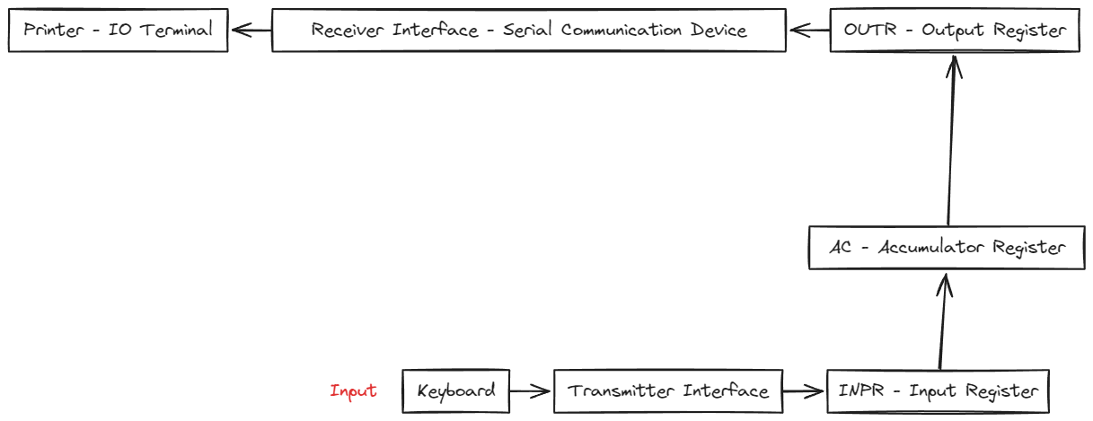
1. Keyboard
- Input Device: The keyboard serves as the primary input device. When a user presses a key, it generates data (keystrokes) in a specific format, typically ASCII or Unicode.
- Signal Transmission: This data is sent to the transmitter interface for further processing.
2. Transmitter Interface
- Data Encoding: The transmitter interface prepares the raw data from the keyboard for transmission. It may perform operations like serializing (converting parallel data into serial form) or encoding for communication over a serial link.
- Forwarding to INPR: The serialized data is passed to the computer’s input register.
3. INPR (Input Register)
- Temporary Storage: The Input Register (INPR) holds the data temporarily until the central processing unit (CPU) or a specific control circuit retrieves it.
- Interface with the Accumulator (AC): The INPR passes the data to the accumulator (AC), which is the core working register in most computing architectures.
4. AC (Accumulator Register)
- Processing Unit Register: The AC is used for computations and data manipulation. Here, the input data is either:
- Processed as part of a larger computation.
- Directly prepared for output through the OUTR.
- Data Control: The AC acts as a central register, ensuring data integrity and sequence before it is sent to the OUTR.
5. OUTR (Output Register)
- Output Preparation: The Output Register (OUTR) holds the processed data temporarily before it is sent to the receiver interface.
- Data Queueing: It ensures that the receiver can fetch data in a synchronized manner without overflow or underflow errors.
6. Receiver Interface
- Serial Communication Device: The receiver interface converts the data back into a format suitable for the printer (usually parallel or specific serial commands).
- Synchronization: It handles any required signal synchronization and ensures the data is properly received and transmitted.
7. Printer
- I/O Terminal: The printer represents the final output device. It takes the processed data and performs the desired action, such as printing the character or command received.
- Feedback Loop (Optional): Some systems have feedback to inform the upstream components (receiver or OUTR) of errors like paper jams or low ink.
Overall Workflow
- The keyboard generates data when a key is pressed.
- The transmitter interface processes and serializes the data for communication.
- The INPR temporarily holds the serialized data until the AC retrieves it.
- The AC processes the data or prepares it for output.
- The OUTR queues the processed data for delivery.
- The receiver interface deserializes and formats the data for the printer.
- The printer produces the final output.
Significance
This model is a simplified representation of how data flows in a serial communication system with input and output devices. It demonstrates key principles such as:
- Registers for Intermediate Storage: INPR, AC, and OUTR ensure efficient and synchronized data handling.
- Interfaces for Data Conversion: The transmitter and receiver interfaces manage transitions between devices with different data formats or communication protocols.
- I/O Processing Pipeline: The system follows a clear sequence from input to processing to output.
This structure ensures reliable and orderly data handling, which is fundamental in both simple systems (like a keyboard-printer setup) and complex computing architectures.
Control Unit
Hardwired Control
Literal hardware IC’s that represent Boolean logic that are made of transistors, gates. These hardware then comprise literal Logic that one writes in pseudocode.
Microprogrammed Control
Programming to get the desired pseudocode’s output is Micro Programmed control. This Logic can be changed easily obviously so these are faster.
Basic Operational Concepts
Primary function of a computer is to execute a program. Data that exists needs processing and the result needs to be stored. To store we use registers.
Registers
There are various types of crucial registers:
- Program Counter ( PC ) :
- Monitors Execution of instructions. Keeps track of which instruction and the next instruction.
- Stores the instruction address.
- Accumulator :
- Operations need to store some values temporarily such as carry value in addition. These values are stored in the accumulator.
- Instruction Register:
- Stores the value at the Instruction Address
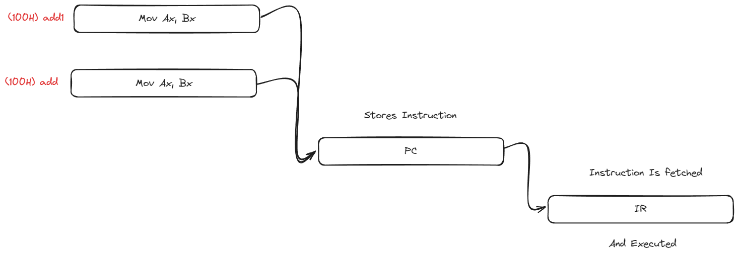
- Stores the value at the Instruction Address
I/O Responding
Polling Of Ports
For example imagine Uday is sitting in his PG and his friend is going out. Now a concern arises if his friend gets into trouble he needs to notify Uday. So he has a remote to turn a light on in his room which will notify him. Now Uday is studying for his ReExams so he will be studying. But he will be checking his light. This rate of him checking this light is Polling Rate.
Similarly A CPU too checks all the ports for active signals. And if there is an active signal it will then monitor and process that.
This falls under continuous monitoring
Interrupt
Imagine a teacher teaching in a class. He is saying a sentence. Mid sentence a student gets a doubt regarding the concept. Instead of not completing his sentence he will complete it and then move to process the students request. This is called Interrupt.
Similarly A CPU follows this and if someone raises their voltage they monitor their data and process it.
This falls under Service on Request.
Parameterizing Processes
Von Neumen Method
Memory, Instruction reside together at the same memory address.
Harvard Architecture
Memory, Instruction reside in different memory addresses.
other bits to study
- Serial Communication
- Parallel Communication
Continued to Computer Organization and Architecture Lecture 6
Information
- date: 2025.01.15
- time: 09:07